Knowledge
Tooth Profile Modification Design
We know that the three key elements of gear tooth profile modification design are: modification amount, modification curve and modification height. Then, how are the three variables determined during tooth profile modification design? And what design considerations are there during tooth profile modification design?
1) Determination of the tooth profile modification amount
According to the principle of tooth profile modification, it is mainly to compensate for the impact caused by the elastic deformation of the gear teeth and manufacturing errors when the teeth mesh in or out. Therefore, the tooth profile modification amount can be approximately determined based on the elastic deformation amount of the gear teeth, while considering a certain manufacturing error.
According to the definition of gear meshing stiffness, the elastic deformation amount of the gear teeth can be approximately calculated by the following formula:
For spur gears

For helical gears

δa - Elastic deformation of gear teeth, μm;
KA - Usage factor, refer to ISO6336-1;
wt - Unit tooth width load, N/mm, wt = Ft / b;
Ft - Tangential force on the gear, N;
b - Effective tooth width of the gear, mm;
c’ - Stiffness of single pair of tooth meshing, N/(mm·μm);
cγ - Average meshing stiffness, N/(mm·μm).
The definition and calculation of meshing stiffness can be referred to ISO6336-1. Or for approximate calculation, for spur gears, the meshing stiffness value of a single pair of teeth, c', can be taken as 20 N/(mm·μm), and for helical gears, the average meshing stiffness value, cγ, can be taken as 25 N/(mm·μm).
When designing tooth profile modification, the tooth profile modification amount should take into account not only the elastic deformation of the gear teeth but also the influence of manufacturing errors. Among them, the manufacturing error can be approximately replaced by the individual pitch error fpt in the gear manufacturing accuracy. Then, the tooth profile modification amount Ca can be expressed by the following formula:

2) Tooth profile modification curve
Tooth profile modification curves are divided into linear modification and parabolic modification. Linear modification is suitable for constant load and light load conditions; parabolic modification is suitable for variable load conditions, and the transition of the parabolic modification curve is smoother, making it more commonly used. Both parabolic and linear modification curves can be uniformly expressed by the following formula:

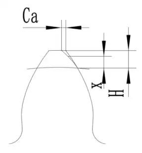
Ca - Profile modification amount;
Cax - Profile modification amount at a distance of x from the starting point of profile modification;
x - Distance from the starting point of profile modification (expressed in the extended distance of involute);
H - Profile modification height (expressed in the extended distance of involute);
m - Exponent, when m = 1, it is linear modification, when m = 2, it is parabolic modification.

3) Determination of the Profile Shaping Height
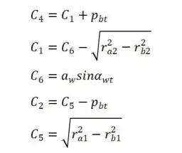
Depending on the different profile shaping heights, profile shaping can be classified into long shaping and short shaping. Long shaping has its shaping starting point at the intersection of single and double tooth meshing; short shaping has its shaping starting point at half the height of long shaping (one base pitch length is retained unshaped on the meshing line). The starting point diameters for long shaping and short shaping can be calculated using the following formulas:
Calculation of the starting point diameter for long shaping:
Small Gear:

Big Gear:

Calculation of the starting diameter for short repair shaping:
Small Gear:

Big Gear:


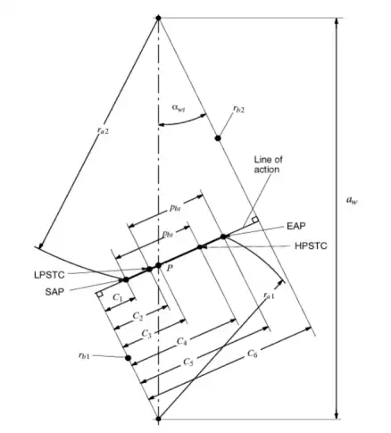
Pbt - End face base circle pitch;
rb1, rb2 - Base circle radii of the smaller and larger gears;
ra1, ra2 - Addendum circle radii of the smaller and larger gears;
aw - Working center distance;
αwt - End face meshing angle;
The meanings of each symbol are shown in the following figure.

In addition, sometimes to simplify the calculation, the profile modification height can also be approximately determined based on the module mn. The modification height H = 0.3 to 0.5 mn (in the radial direction), and then the starting diameter of the profile modification can be calculated using the following formula:

dFa - Effective addendum circle diameter, that is, the addendum circle diameter minus the addendum chamfer part.
Under conditions of light load or small overlap, and when the load varies, H takes a smaller value; under conditions of heavy load or large overlap, and when the load is constant, H takes a larger value.
4) Other design considerations for tooth profile modification:
l Top land chamfering should not be considered as a part of tooth profile modification.
l The top land modification of the driven gear is usually greater than that of the driving gear.
l Modifying the top land of one gear has the same effect as modifying the root of the mating gear.
l Excessive top land modification will reduce the gear's contact ratio, so the change in contact ratio under light load should be checked.
l When the tooth profile modification is large, root modification will reduce the tooth thickness at the root and is prone to forming steps, which will affect the bending strength of the gear.
If any question or any demands we can help, please feel free to contact us at info@castings-forging.com


