
Knowledge
Optimization of Casting Process for Integral Cast Steel Axle Housing
In response to the shrinkage cavity defect in the boss of the integral axle housing support and the deformation in some areas of the casting, the casting process was optimized. The integral axle housing was modeled in 3D using Creo software, and the casting process was simulated using numerical simulation software. The simulation results reflected the locations of shrinkage cavity and porosity defects in the casting. Based on the previous trial production results, the original process plan was optimized. Through the simulation results and the trial production of samples, the optimized plan effectively reduced the shrinkage cavity defects and deformation out-of-tolerance, and improved the product qualification rate.
The integral axle housing is mainly applied to the load-bearing axles of special vehicles and is one of the core components of the axle system. Its working conditions include high-altitude, saline-alkali, desert and other multi-terrain and multi-latitude regions. Under full load, it needs to withstand high impact loads. For a certain type of integral axle housing cast steel part, due to the isolated hot spots at the support and other parts, it is difficult to obtain a dense structure, which affects the mechanical properties of the integral cast axle housing and fails to meet the requirements of the casting usage.
This type of integral axle housing is made of ZG40Mn material. The structure of the casting is shown in Figure 1, with dimensions approximately 2160mm × 400mm × 314mm, wall thickness ranging from 15mm to 25mm, and the weight of the casting blank is about 300kg.

Figure 1 Schematic of the three-dimensional model of the casting
-----------------------------------------------------------------
1. Original Process Plan and Analysis
Figure 2 shows the original casting process plan for the integral axle housing. This plan employs sodium silicate sand technology with a two-box molding process. The surface of the sand mold and core is coated with alcohol-based paint twice. A φ70mm riser is placed above the axle housing, and a 230mm×75mm oval internal riser is set above the support of the axle housing. Two φ120mm×200mm risers are placed at the ends of the axle housing for the steering knuckle ports. Holes smaller than φ30mm are not cast. This casting uses a conventional bottom-up pouring system, with the sprue and inner gates located on the parting surface. The cross-sectional area ratio of the pouring system is ∑A_dir:∑A_sprue:∑A_gate = 1.0:2.0:1.4. All these settings are conducive to the feeding and solidification of the casting.
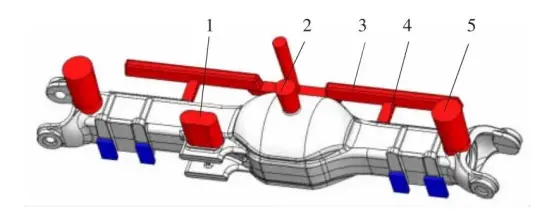
Figure 2 Original Casting Process Plan
-----------------------------------------------------------------
2. Problems and Analysis
Simulation of the original process and combination with actual production revealed the following issues with the original process plan:
1) After drilling the castings produced by the original process at the convex platform of the side wall tube, some shrinkage cavities were found in the holes. As shown in Figure 3, isolated liquid phase zones existed in the bridge housing support when the solid fraction was above 75%, which was highly likely to cause defects. After drilling the trial production products on site, it was confirmed that there were some minor shrinkage cavities and porosity defects in the support part.
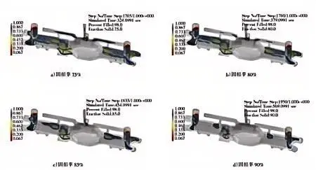
Figure 3 Solidification simulation results of the original process scheme
-----------------------------------------------------------------
2) There are defects in the thrust rod support. As shown in Figure 3, due to the position of the riser 1, the bottom of the thrust rod support of the casting cannot be filled properly. After drilling, it was found that there were some shrinkage cavity defects.
3) Due to the length of the casting itself being approximately 2160mm and the original casting process design of the straight-through gating system, during processing, some of the axle housings had out-of-tolerance deformation and were unprocessable.
The simulation results show that: As the bridge package of the axle housing is relatively thin and solidifies first, the tube walls on both sides of the axle housing solidify successively. When the solid fraction reaches 75% to 90%, isolated liquid zones appear in the parts shown in Figure 4, and these isolated liquid zones successively appear inside the casting. The risers cannot provide effective feeding, which easily leads to shrinkage cavities or porosity defects in these areas after solidification.
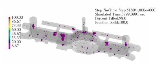
Figure 4 Shrinkage cavity and porosity criterion of the original process plan
-----------------------------------------------------------------
3. Process Improvement Measures and Results
In response to the shrinkage cavity and porosity defects that occurred in the support or boss areas during the simulation results and trial production, the existing riser dimensions were adjusted accordingly, and external chills were used to regulate the temperature field around the casting. For the deformation of some castings, some of the horizontal runners were changed to a zigzag shape to reduce the impact of the gating system on the casting's shrinkage deformation, as shown in Figure 5:

Figure 5 Improved Casting Process Scheme
-----------------------------------------------------------------
1) Enlarge the No. 1 riser in Figure 2 to 230mm×90mm×150mm to enhance the feeding capacity of the riser.
2) Add two side risers with a size of φ100mm×250mm to the No. 4 runner and the side boss of the casting in Figure 2 to increase the feeding capacity of the risers to the hot spots of the casting.
3) Increase the number of inner gates of No. 4 runner in Figure 2 to 4, and change the No. 3 transverse runner to a zigzag shape to reduce the deformation tendency of the slender casting.
4) Add multiple external chills to the side bosses of the axle housing to adjust the temperature field of the casting and increase the chilling effect on the thick and large parts of the bosses, which is beneficial to adjust the solidification sequence of the casting and reduce the accumulation of concentrated defects.
5) Adjust the size of the axle housing model, increase the correction amount of the outer skin of the bridge package model by 1mm, and increase the overall correction amount of the side size of the main reduction assembly surface end port by +2mm to reduce the situation where the end face of the axle housing cannot be drilled due to deformation exceeding the tolerance.
The solidification simulation results of the integral axle housing optimization scheme shown in Figure 6 indicate that there are no isolated liquid zones inside the casting during the solidification process, and the risers are the last to solidify. The defects are all moved to the interior of the risers. After the improvement of the casting process, except for some discrete defects, there are no obvious defects in the casting body.
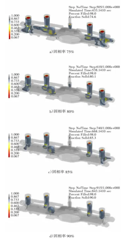
Figure 6 Solidification simulation results of the integral axle housing optimization scheme
-----------------------------------------------------------------
4. Actual Production Verification
The actual casting of a single product is shown in Figure 7. It consumed approximately 450 kg of molten steel, of which the casting weighed about 280 kg, and the process yield of the casting was approximately 62%. A total of 6 castings were produced in the first batch of trial production. After processes such as shakeout, cutting, cleaning, and grinding, the castings were inspected for appearance, non-destructive testing, and water pressure leakage tests. The test results were good and met the usage requirements. Additionally, one bridge housing was randomly selected for cutting verification. No visible defects were found upon visual inspection, and the flaw detection was qualified.
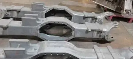
Figure 7 Finished Casting Product
-----------------------------------------------------------------
5 Conclusion
In response to the partial defects that occurred in the castings during the initial trial production, the initial casting process plan for the integral axle housing was simulated using numerical simulation technology, and the process was modified and verified through trial production. The results show that:
1) By increasing and enlarging the risers, adding external chill irons, and adopting the optimized gating and risering system, the internal quality of the castings was effectively improved, and the shrinkage cavity and porosity defects of the castings were well controlled. The process yield of the castings was 62%, and the shrinkage cavity defects of the integral axle housing castings were well controlled.
2) Through the trial production of sample parts, it was verified that the numerical simulation software can accurately simulate the defect positions during the solidification process and optimize the process plan based on the defect positions in the original plan, keeping the casting defects within the acceptable range of the enterprise. The improvement of the casting process through numerical simulation and the trial production of sample parts can help enterprise technicians enhance their casting development capabilities and reduce the risks of new product development.


