Knowledge
High-frequency Induction Quenching Process and Its Implementation In Practical Applications
There are two types of high-frequency quenching heating methods: The first one is simultaneous heating and quenching, which involves heating the surface of the workpiece that needs quenching simultaneously and then rapidly cooling it; the second one is sequential continuous heating and quenching, where a small part of the surface of the workpiece is heated by induction heating, while the workpiece moves downward, allowing for sequential and continuous heating and cooling of the surface.
When producing multi-variety and small-batch parts, different materials may require different quenching media. Therefore, the quenching method of simultaneous heating is mostly adopted. For parts with large quenching surface area, due to the limitations of equipment power and other factors, the continuous heating method is considered for quenching.
1. High-frequency surface quenching of the inner hole of the martensitic stainless steel workpiece
(1) Processing difficulties
The processing difficulty of high-frequency surface quenching of the inner hole of martensitic stainless steel workpiece is achieved by simultaneous heating. The main difficulties lie in the stainless steel material and the surface quenching of the inner hole.
During the process of high-frequency induction heating, when the temperature exceeds the demagnetization point of the material (the demagnetization point of steel materials is generally around 700-800℃), the electromagnetic induction capacity of the material decreases, and the heating speed drops by several times. Further heating becomes difficult. For stainless steel, the heat treatment temperature is high, generally above 1000℃, and heating to the quenching temperature of the material is even more challenging. On the other hand, due to its high heat treatment temperature, which is close to the melting point of the material, although the heating speed above the demagnetization point decreases, it is still faster than that of conventional heat treatment, and it is difficult to control, posing a risk of overheating and melting of the surface of the parts.
The annular effect is one of the three major effects of induction heating and is also the reason for the difficulty in heating the inner hole. Even when using an induction coil to heat the workpiece, the current passing through the induction coil concentrates on the inner surface of the coil. When heating the outer surface of the workpiece, the inner surface of the induction coil corresponds to the outer surface of the workpiece, which is conducive to the heating of the workpiece. However, when heating the inner hole surface of the workpiece, the direction is exactly opposite, which significantly reduces the electrical efficiency of the induction coil and is not conducive to the heating of the workpiece. Moreover, when performing induction quenching on the inner hole of the workpiece, the heating surface is inside the workpiece, and it is not easy for the operator to directly observe from the outside. This increases the operational difficulty to a certain extent.
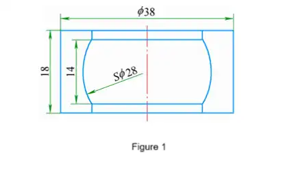
For the spherical bearing of a certain product (as shown in Figure 1), it is required to perform spherical quenching with a diameter of 28mm. The material is martensitic stainless steel 20Cr13, and the quenching hardness should be within the range of 35 to 45 HRC. Besides the aforementioned heating difficulties, this workpiece has a spherical heating surface instead of a straight-through inner hole, which inevitably leads to an increase in the gap between the inductor and the heating surface of the workpiece. This further reduces the electrical efficiency. Usually, for internal hole high-frequency quenching, in order to overcome the adverse effects of the annular effect on the heating of the workpiece, a magnetic conductor is set on the inductor to change the distribution of the magnetic field and force the current to distribute closer to the surface where the workpiece needs to be heated, thereby improving the heating effect. However, the inner hole of this workpiece is relatively small. Removing the gap distance between the inductor and the workpiece as well as the size of the inductor itself, the inner diameter of the inductor is less than 13mm, making it impossible to install a magnetic conductor. For the induction quenching of this workpiece, the only way is to optimize the process parameters and improve the heating process to maximize the equipment's capacity.

(2) Quenching Process Scheme
The quenching process scheme includes heating time, quenching temperature and quenching medium.
Many people believe that high-frequency induction quenching belongs to instantaneous heating and can reach the quenching temperature within just a few seconds. This understanding reflects the general situation but is not comprehensive. In some cases, the heating speed will be slower. In some special circumstances, by reducing the voltage output and other means to slow down the heating speed of the parts, it can meet the needs of some special workpieces or special technical requirements. For this workpiece, due to the existence of many unfavorable factors, rapid heating is not feasible. Considering the need for visual temperature changes and preventing overheating or even surface melting phenomena to ensure the quenching quality, in order to guarantee the quenching quality, it is necessary to base on a slower heating speed. If the heating speed is too slow, the advantage of surface quenching will be lost, and due to heat conduction, the hardened layer will be too large. Practice has proved that controlling the heating time of this workpiece within 2.5 to 3 minutes is relatively appropriate.
The quenching temperature of the workpiece should be determined based on the steel type, the original microstructure and the heating rate in the phase transformation zone. Under certain conditions where the steel type and the original microstructure are fixed, the quenching temperature is mainly determined by the heating rate. The faster the heating rate, the higher the required quenching temperature. The heating rate for high-frequency quenching is much higher than that for conventional heat treatment, so the quenching temperature for high-frequency quenching is generally higher than that for conventional heat treatment. For spherical bearings, due to various reasons, there are many difficulties in heating, and the quenching temperature should not be too high. The higher the quenching temperature, the greater the difficulty in achieving it. This is also one of the reasons for choosing a slower heating rate. Although a slower heating rate was selected, it still belongs to rapid heating. Considering a slower heating rate means that the austenitization time is longer than that of rapid heating. After comprehensive analysis of various factors, the quenching temperature should be equivalent to or slightly higher than that of conventional heat treatment.
Martensitic stainless steel has good quenching properties. When the workpiece size is not very large, it can be fully quenched by air cooling alone. The effective thickness of spherical bearings is less than 10mm and they are surface-hardened. Theoretically, air cooling quenching should be selected. At the same time, considering the special situation of choosing a lower quenching temperature, in order to ensure the quenching effect of the workpiece and meet the hardness requirements, air cooling quenching inevitably has certain uncertain factors. Choosing a faster cooling medium for quenching and compensating for the possible defect of a lower quenching temperature becomes an inevitable choice. The cooling speed of oil is significantly better than that of air cooling. Among various quenching media, it is one of the slower ones. After the workpiece is heated to the quenching temperature and immediately immersed in oil for quenching, the quenching effect can be achieved. The slower cooling speed does not cause defects such as cracks, and it can stably and effectively meet the technical requirements.
(3) Actual Effect
After the spherical bearings were quenched according to the above scheme, the hardness of the spherical surfaces was above 45HRC. After quenching and tempering at 480℃, the hardness remained above 40HRC, and the hardness distribution of each workpiece and each part of the workpiece was uniform and stable, indicating that the workpieces fully met the quenching requirements. The success of the quenching of this workpiece provides a beneficial reference for the quenching of stainless steel workpieces with high heating difficulty and the surface quenching of inner holes.
2. Deep hardening layer surface quenching of larger-sized parts
(1) Processing difficulties
The surface quenching of this workpiece also adopts the simultaneous heating method. The main processing difficulties lie in the limitations imposed by the equipment power and current frequency.
High-frequency quenching involves rapid heating over a short period of time, requiring the material to be heated to a very high temperature within a short time. Adequate heating power is necessary as a foundation. The larger the heated surface of the workpiece, the greater the required power. When the heated surface is large enough, it becomes difficult to achieve simultaneous heating smoothly due to the power limitation of the equipment.
When the workpiece undergoes induction heating, the penetration depth of the current is determined by the current frequency. This principle makes the current frequency the main factor determining the depth of the hardened layer. The current frequency of high-frequency quenching equipment is generally fixed. For example, the current frequency of high-frequency equipment is 200-300 kHz, corresponding to a thermal penetration depth of 0.9-1.1 mm. This limits the further deepening of the hardened layer depth.
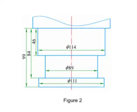
The traction pin of a certain product (as shown in Figure 2 for the quenching part) is a key component of the product. It is made of 40Cr alloy structural steel and requires high-frequency quenching on the outer round surface with a diameter of 89mm. The quenching hardness should be between 50 and 60 HRC, and the depth of the hardened layer should be 2.5 to 4.5mm. This workpiece requires a larger quenching surface size. Besides the need for a larger power for heating, the more significant problem affecting the heating is that the quenching part is the concave groove of the workpiece. The production of the induction coil is also a major difficulty. If the induction coil is made by the conventional method, that is, the inner diameter of the induction coil is slightly larger than the diameter of the quenching surface, then the induction coil must be made on-site, which is very troublesome. Moreover, the workpiece can only be quenched after damaging the induction coil, and each workpiece requires a corresponding induction coil for high-frequency surface quenching, which also has the problem of manufacturing error for each induction coil. If the inner diameter of the induction coil is greater than the adjacent cross-sectional diameter, that is, greater than 111mm, then the distance between the induction coil and the quenching part increases by 11mm, and the heating efficiency of the induction will be significantly reduced. Regarding the depth of the hardened layer, the range of 2.5 to 4.5mm is 2.5 to 4.5 times the normal thermal penetration depth. To increase the depth of the hardened layer, generally, the principle of heat conduction can be utilized, that is, by taking advantage of the characteristic that heat is conducted from the surface to the center, the thickness of the heating layer can be increased. However, relying solely on the method of heat conduction requires a large temperature difference from the surface inward. Often, when the required depth of the hardened layer reaches the quenching temperature, the surface temperature is already too high, resulting in defects such as overheating and overburning of the surface structure.

(2) Quenching Process Scheme
To complete the quenching of this workpiece, an induction heater was specially fabricated, and the process control was strengthened by adopting intermittent heating mode.
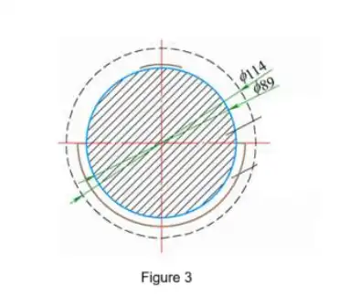
Taking into account the various characteristics of the traction pin, we changed the traditional production method of the sensor and made the sensor in the form of a semi-circle. This overcomes the aforementioned difficulties of the traditional sensor in performing high-frequency quenching on this workpiece. It can achieve the best possible distance match between the sensor and the heating surface, and it is also convenient to separate the workpiece from the sensor for quenching. In the specific operation implementation, the workpiece is rotated concentrically relative to the sensor to achieve instantaneous heating of the semi-circle and the overall heating of all the quenching surfaces (see Figure 3).

As has been mentioned earlier, when steel materials are heated to a certain temperature, they will lose their magnetism and the heating speed will decrease by several times. During the actual heating process, when a thin layer exceeding the demagnetization point appears on the surface, the intensity of eddy currents at the junction adjacent to this thin layer will suddenly increase, becoming the part with the fastest heating speed. There will be a phenomenon where the heating speed of the high-temperature surface layer decreases while the junction heats up more rapidly and moves inward. This phenomenon is beneficial for increasing the depth of the hardened layer, but the heating speed of the high-temperature surface layer is much faster than that of the junction area within the layer. The tendency of overheating and overburning in the surface layer is still very serious. At this time, it is necessary to find the optimal configuration of parameters such as voltage and heating speed, strictly control the heating process, and try to increase the depth of the hardened layer while ensuring the quality.
The requirement for the depth of the hardened layer of the traction pin is quite large. Although the parameters alone are sufficient to fully meet the technical requirements, there is still a deficiency in terms of other techniques. Intermittent heating is adopted, that is, when the temperature has not reached the quenching temperature, the heating is temporarily stopped to allow more heat from the surface to conduct inward. Then, the heating is resumed. This is equivalent to increasing the heat conduction time and reducing the temperature gradient from the surface to the interior. This process is repeated several times to ensure that the surface temperature does not rise too high and does not cause overheating or overburning. The purpose is to achieve a more uniform attainment of the quenching temperature within 2.5 to 4.5 mm from the surface inward.
(3) Actual Effect
After taking measures such as improving the design of the sensor, optimizing the process parameters, and intermittent heating, the surface hardness of the traction pin after high-frequency quenching can be stably maintained at around 55HRC, with the depth of the hardened layer being more than 3mm. The use of high-frequency quenching has met the depth requirement of the hardened layer suitable for medium-frequency quenching. Moreover, due to the improvement of the sensor, the workpiece can be quenched continuously and one by one, effectively improving the work efficiency.
3. Matters to be noted
To ensure the processing quality, the following points should be taken into consideration:
(1) Equipment maintenance is of utmost importance. The distance between the high-frequency inductor and the workpiece should be kept as small as possible to minimize the electrical energy loss and ensure the maximum power requirement for simultaneous heating.
(2) The most common form of the inductor is made by bending copper tubes into a spiral shape. When designing and manufacturing such inductors, larger-diameter copper tubes should be used as much as possible and the number of turns should be reduced to lower the inductive reactance and ensure the heating efficiency.
4. Conclusion
High-frequency induction quenching is a complex process and falls under the category of special heat treatment in heat treatment. Moreover, achieving simultaneous heating is even more challenging. In the actual operation, various factors such as equipment power, working frequency, inductor, heat treatment parameters, material microstructure transformation, quenching medium, and cooling method must be comprehensively considered to achieve the optimal coordination of these factors. This will maximize the potential of the equipment and meet the needs of simultaneous heating and quenching of multiple varieties and small-batch workpieces as much as possible.
If you have any questions, please feel free to contact us at info@castings-forging.com


