Knowledge
Gear Failure (I)
Gears are the core components of mechanical transmission systems, and their reliability directly affects the operational life and safety of equipment. However, under high-speed, heavy-load or harsh working conditions, gears often fail due to various reasons, such as fracture, leading to equipment downtime or even safety accidents. Pitting is also a common failure mode of gears, which can reduce transmission efficiency, increase noise, and even cause complete gear failure.
This article mainly discusses the failure modes, causes, detection methods, and preventive measures of gear fracture and pitting, providing references for gear design, manufacturing, and maintenance.
I. Gear fracture failure
According to the fracture characteristics and mechanisms, gear fractures can be mainly classified into the following types:
1.1 Fatigue Fracture
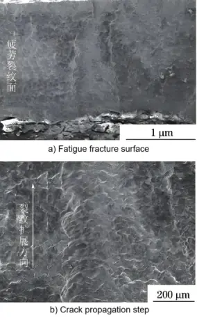
Characteristics: Cracks initiate from the tooth root or tooth surface and gradually expand until fracture. The fracture surface shows "beach marks" or "shell marks" features.
Causes:
- Stress concentration under cyclic loading (such as an insufficient fillet radius at the tooth root).
- Internal material defects (inclusions, pores).
- Improper surface treatment (such as uneven carburized layer depth).
1.2 Overload Fracture
Characteristics: The fracture surface is rough, with no obvious fatigue expansion zone, and it is generally a one-time fracture.
Causes:
o Instantaneous overload (such as impact load or locked rotor).
o Insufficient design strength (too small module or low material yield strength).
1.3 Brittle Fracture
Characteristics: The fracture surface is smooth and presents a radial or herringbone pattern, commonly seen in gears at low temperatures or with high hardness.
Causes:
- Poor material toughness (e.g., quenched but not tempered).
- Hydrogen embrittlement (not dehydrogenated after electroplating or acid washing).
1.4 Corrosion Fatigue Fracture
Characteristics: The fracture surface is covered with corrosion products, and the cracks mostly originate from corrosion pits.
Cause:
o The gear is subjected to alternating stress in a corrosive environment (such as seawater, acid mist).
II. Gear Fracture Failure Analysis
2.1 Macroscopic Inspection
Fracture surface morphology: Observe whether there are fatigue striations, dimples or brittle features on the fracture surface.
Crack origin: Determine the crack initiation point (usually located at the tooth root, tooth surface or internal defect).
2.2 Microscopic Analysis
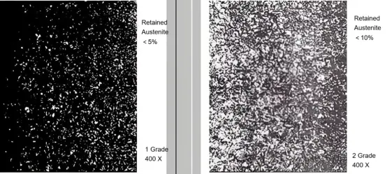
Metallographic examination: Check the material structure (such as whether the quenched martensite is overheated or whether there are non-metallic inclusions).

SEM/EDS analysis: Observe the microstructure of the fracture surface through scanning electron microscopy and combine energy spectrum analysis to determine the composition of corrosion or inclusions.

2.3 Mechanical Properties Testing
Hardness Test: To determine if the depth of the surface hardened layer meets the standard (for example, the surface hardness of carburized gears should be 58 to 62 HRC).
Impact Test: To evaluate the low-temperature toughness of the material (especially for gears used in cold environments).
2.4 Load and Operating Conditions Review
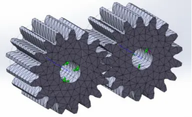
Finite Element Analysis (FEA): To simulate the forces on the gear and verify if the stress concentration areas match the origin of cracks.

Vibration monitoring data: Check if there are any abnormal vibration or shock load records before failure.


