Knowledge
Gear Accuracy (Part Two)

Precision control in gear manufacturing
3.1 Process Chain Precision Allocation
Typical process chain precision attenuation curve:
Machining → Heat treatment → Finishing → Assembly
↓2 grades ↓1 grade ↑0.5 grade ↓0.3 grade
Capability index requirements for each process:
- Hobbing: Cp ≥ 1.33
- Grinding: Cp ≥ 1.67
- Lapping: Cpk ≥ 1.25
3.2 Key Process Control Points
3.2.1 Tooth Profile Accuracy Control
- Tool accuracy: AA grade hob (DIN 3968)
- Machine thermal compensation: Temperature rise ≤ ±0.5℃/h
- Clamping rigidity: Radial runout ≤ 0.005mm
-
3.2.2 Heat Treatment Deformation Control
Process Comparison Process Deformation
|
Process |
Deformation (mm) |
Hardness Gradient |
Production Cost Coefficient |
|
Vacuum Carburization |
15-30 |
Smooth |
1.8 |
|
Ionic-nitriding |
5-15 |
Steep |
2.5 |
|
Induction Hardening |
30-50 |
Abrupt |
1.2 |
3.3 Advanced Manufacturing Technology
Dry cutting process (high-speed hard milling)
o Linear speed: 250 - 400 m/min
o Surface roughness Ra ≤ 0.8 μm
Form grinding technology
o CBN grinding wheel grit size: 80/100
o Truing compensation algorithm (R parameter model)
Laser-assisted processing
o Local preheating temperature: 300 - 450 °C
o Cutting force reduced by 40%
Gear accuracy inspection and evaluation
4.1 Evolution of Inspection Methods
The inspection methods for gears have evolved from traditional geometric measurement to comprehensive error measurement, and then to modern non-contact measurement.
Traditional geometric measurement
In the early days, coordinate-based geometric analytical measurement methods were adopted. By establishing a measurement coordinate system, discrete coordinate points or continuous trajectory scanning measurements were conducted on the gear tooth surface, mainly detecting single geometric deviations such as tooth profile, tooth direction, and tooth pitch. This method relied on mechanical instruments (such as involute checking instruments) to assess the processing quality by comparing the actual tooth surface with the theoretical trajectory.
Comprehensive error measurement
In the mid-20th century, the meshing rolling comprehensive measurement method was developed. This method detects the tangential comprehensive deviation and radial comprehensive deviation by simulating the gear meshing process. It is fast and suitable for quality control in mass production. Moreover, it can decompose the radial comprehensive helix angle deviation and the tooth direction taper deviation, thereby enhancing the measurement accuracy.
Modern detection technology
With the development of photoelectric technology, industrial CT and others, non-contact measurement has become mainstream. For instance, industrial CT can achieve three-dimensional error analysis. Combined with technologies such as spectral analysis, it can more accurately diagnose gear processing issues. Modern instruments also automatically process data through computer-aided systems, enhancing detection efficiency and intelligence levels.
4.2 Modern Inspection Equipment
Key technical parameters of gear measuring center:
- Resolution: 0.1 μm
- Rotation accuracy: ≤ 0.5"
- Scanning speed: 1000 points/second
- Temperature compensation: ± 0.1℃
4.3 Big Data Analysis Applications
SPC Process Control
CpK Trend Chart Monitoring
Multi-parameter Correlation Analysis
Digital twin prediction
Accuracy attenuation model based on historical data
Remaining accuracy life assessment
4.4 Research on the Relationship between Precision and Performance
4.4.1 Influence of Vibration and Noise
Experimental data show that:
- For every 10 μm increase in cumulative pitch error, noise increases by 3-5 dB.
- The correlation coefficient between tooth alignment waviness and the amplitude of the 2nd order vibration reaches 0.82.
-
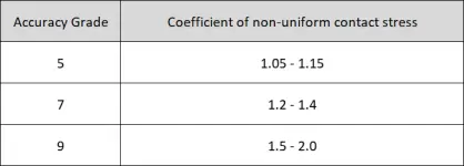
4.4.2 Relationship between Load Distribution and Performance

4.5. Special Gear Precision Requirements
4.5.1 High-speed Gears (Linear Speed > 100 m/s)
- Dynamic Precision Indicators: FFT Harmonic Analysis
- Modification Compensation: Thermal Elastic Deformation Prediction
-
4.5.2 Heavy-duty Gears (Contact Stress > 1500 MPa)
- Micro-geometric Precision: Waviness Wt ≤ 0.5 μm
- Subsurface Integrity: Residual Stress Gradient Control
Conclusion
The development direction of future gear processing and precision control
Intelligent precision compensation:
Machine tool adaptive adjustment system
Digital twin real-time feedback o
Micro-nano precision breakthrough:
Ultra-precision machining (<0.1μm)
Application of quantum measurement technology
Full life cycle precision management:
Wear prediction model
Self-repairing surface technology
Vigor has rich experience and the professional team in producing gears and gear shafts. If anything we can help or any parts you need, please feel free to contact us at info@castings-forging.com


