Knowledge
Exploration of Resin Sand Full Mold Casting Process for Heavy-Duty Ductile Iron Castings
This paper briefly describes the structural features, technical requirements and manufacturing difficulties of heavy ductile iron castings. It elaborates on the casting methods, gating system design methods and manufacturing methods of this type of castings. The process characteristics, production advantages and application scope of resin sand solid mold casting are introduced. Through strict process control, selection of appropriate raw materials, proper spheroidizing and inoculation treatment processes, and special pretreatment techniques during the production process, high-quality large ductile iron castings can be produced. This can provide technical references for the solid mold casting process of similar heavy castings.
Keywords: Heavy ductile iron castings; Solid mold casting; Casting process
Modern casting technology will accelerate its development and improvement in several aspects, such as energy and material conservation, pollution reduction, improvement of casting dimensional accuracy, reduction of casting defects, and adaptation to the development of new casting alloys [1]. Our company has an annual production capacity of 20,000 tons of cast iron parts (excluding centrifugal ductile iron pipes). We keep pace with the development of the casting industry and have successively developed the (furan resin sand + foam pattern solid mold) casting process and vacuum foam pattern casting process, replacing the traditional (wooden pattern + wooden core box) molding and core assembly process with foam pattern solid mold.
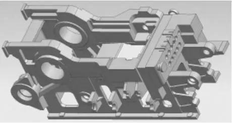
The ductile iron part (QT500-7) we undertook has a gross weight of 18,350 kg, with a main body size of (length × width × height) 3,650 mm × 1,480 mm × 1,230 mm, a main body wall thickness of 100 mm, and the thickest part reaching 450 mm. The assembly surface shape is irregular and has strict quality requirements. There are five blind holes with a diameter of 100 mm and a depth of 170 mm, and six through holes with a diameter of 70 mm and a depth of 540 mm. The order quantity is two pieces, and the overall casting difficulty is relatively high. The part structure is shown in Figure 1. Our company has the production capacity of vacuum foam pattern, resin sand and foam pattern solid mold casting processes. After process analysis and evaluation, it was decided to use the furan resin sand + foam pattern solid mold casting process for production, hereinafter referred to as solid mold casting. This can ensure the delivery time and reduce production costs.

Figure 1 Three-dimensional structure diagram
-----------------------------------------------------------------
1. Solid casting process plan
Solid casting is quite different from ordinary sand casting. The most significant feature of solid casting is that it uses foam pattern instead of wooden pattern. During the pattern design process, technicians do not need to consider parting negative numbers, core heads, positioning, and draft angles for demolding. They only need to add machining allowances and casting shrinkage rates. The pattern-making process is simple. First, the pattern is divided into several pieces, and then the pieces are assembled together. The assembled pattern has high dimensional accuracy, uses less raw materials in the pattern-making process, and has a much shorter production cycle than the wooden pattern. At the same time, it simplifies the molding operation, eliminating the separate molding, core-making, and assembly of the mold and core. The production efficiency is greatly improved. However, if the casting process is not well considered, it may cause specific solid casting defects such as wrinkling, slag inclusion, and porosity.
1.1 Pattern Making Process
1.1.1 Foam Pattern
The foam pattern is exactly the same in shape and structure as the casting. Based on the part drawing, a three-dimensional model of the pattern is created after adding machining allowance and casting shrinkage rate. The pattern is then divided into several modules to ensure that it is easy for workers to cut and save foam boards, and also to facilitate assembly and ensure the dimensional accuracy of the assembled pattern. The foam boards used are cut and shaped by both CNC engraving and electric wire cutting, and then assembled by bonding to form the pattern. To ensure that the pattern has sufficient compressive strength and deformation resistance, polystyrene foam boards with a density of 20-22g/L are selected. The assembled pattern is placed in a special drying kiln for 10-12 hours. The drying temperature is generally controlled at 45-55℃. After drying, the pattern is coated with two layers of water-based cast iron lost foam coating and one layer of alcohol-based graphite coating. The coating method is dipping, and the coating thickness is controlled at 3-3.5mm.
1.1.2 Specialized Foam Core Mold
The middle part of the casting is a large cavity. Due to the large overall contour of the pattern, to ensure sufficient strength at this part during molding, a specialized foam core mold with the exact shape of the cavity is made. During molding, this specialized foam core mold serves as the bottom support to enhance the rigidity of the overall pattern, ensuring that the pattern does not deform during the ramming process. After the mold is made, the box is turned over and the foam core mold is removed. This foam core mold can be reused.
1.2 Process Design
The casting has a large, thick and heavy profile. A two-group open bottom-pouring double-layer stepped gating system is adopted. Local critical areas are equipped with external chill irons to prevent internal shrinkage porosity. The principle of balanced solidification is considered in the process design. The risers and vent holes are set to ensure feeding, slag removal and gas venting.
1.2.1 Gating System Design
When producing thick and large ductile iron castings, it is beneficial to shorten the pouring time as much as possible to reduce the floating of graphite and the accumulation of inclusions [3]. By analyzing the shape and internal structure of the casting, a two-group open stepped gating system is adopted, divided into upper and lower layers. The lower layer gating system is mainly used for filling, while the upper layer gating system is mainly used for slag removal, gas venting and feeding. The two gating systems are distributed on both sides of the foam pattern. The upper layer gating system is introduced at the bottom of the top riser, which is conducive to gas venting and allows the floating slag in the molten iron and the slag produced by the gasification of foam plastic to float up fully, ensuring the feeding effect of the riser and eliminating the surface slag inclusion defects of the casting.
This casting is a heavy cast iron part, and the pouring time can be calculated based on gray iron castings:
t = S2L (1)
In the formula, L represents the total weight of the molten metal in the mold, with a yield rate of 92% calculated, and L is taken as 19,945 kg; S2 is the wall thickness coefficient, taken as 2.2; thus, the pouring time t = 310 seconds, and for two pouring systems, the pouring time is taken as 155 seconds. The pouring time for ductile iron castings can be determined by the calculation method for gray iron castings, and then reduced by 1/3 to 1/2 [1], taking the pouring time t = 90 seconds. According to the pouring time chart for large ductile iron castings, the pouring time is verified, and it can be seen that the selected pouring time is reasonable.
According to the formula for calculating the flow-blocking cross-sectional area:
∑A_block = L / (0.31μPt) (2)
In the formula: the flow coefficient μ is taken as 0.5, Hp is taken as 40 cm, and L = 19945/2 = 9972.5 kg.
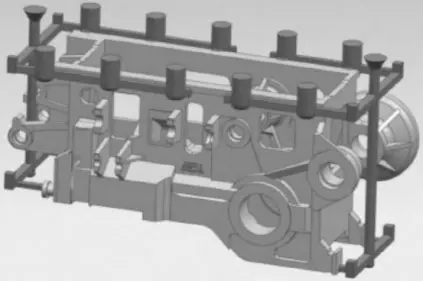
Then, A_block = 9972.5 / (0.31 × 0.5 × 90) ≈ 113 cm². As the minimum flow-restricting section of the open gating system is the sprue, a ceramic tube with a diameter of Φ120mm is selected for the sprue through calculation. The cross-sectional area ratio of each component of the gating system is set as A_sprue : A_transverse : A_inlet = 1 : (1.2 - 2.0) : (1.5 - 2.0). Therefore, the cross-section of the transverse runner is selected as 150mm × 120mm; the cross-section of the inlet runner is selected as a trapezoidal shape with two single groups, with the upper base of the trapezoid being 110mm, the lower base being 140mm, and the height being 80mm. The actual cross-sectional area ratio of the gating system is approximately A_sprue : A_transverse : A_inlet ≈ 1 : 1.6 : 1.8. The layout diagram of the gating system is shown in Figure 2.

Figure 2 Schematic Diagram of the Pouring System Layout
1.2.2 Design of External Chills
For castings with thick walls, external chills are used in critical and thick areas to prevent shrinkage porosity defects and achieve balanced solidification. During production, the usage frequency of chills should be strictly controlled. The surface of chills must be smooth without rust or holes [4]. Before each use, they should be shot blasted and coated with a layer of alcohol-based coating. They should fit tightly with the casting surface without any gaps.
1.2.3 Design of Risers and Venting
Design principle: Ensure that the thick areas are effectively compensated for shrinkage. As the casting is a thick and large piece, compensating risers are used for shrinkage compensation to obtain qualified castings [5]. Ten compensating risers with a diameter of 280mm and a height of 400mm are placed on both sides of the upper surface of the casting. The upper horizontal runner and the inner runner pass through the risers, allowing hot molten iron to be collected in the risers and ensuring that slag can float and be discharged, thus achieving the combined effect of compensation, slag removal, and venting.
The internal venting channels of the foam pattern and the external venting channels of the mold are two process measures to improve the gasification conditions of the pattern and accelerate the complete escape of gases from the mold. For thick and large castings, in addition to placing risers on the upper surface of the casting, multiple external venting channels can be set inside the mold and along the outside of the foam pattern. Before the top box is closed, venting channels are opened inside the pattern in the thick areas of the top of the casting to ensure that the gasified gases in the mold cavity can be discharged in time during the initial stage of pouring.
2 Molding Process Control
The addition of resin is controlled at 0.9% to 1.2%, with the upper limit for large castings and cores. First, the special foam core is fixed on the molding platform, and the foam pattern is placed on the special foam core to make the lower mold. After complete curing, the box is turned over, and the special foam core is removed before making the upper mold.
For the blind holes and long through holes at the front end of the casting, specially made hole-forming core rods are pre-embedded in each hole. The hole-forming core rods are made by joining ceramic tubes of a size equivalent to the blind holes and long through holes, filling them with resin sand, inserting steel bars in the middle, compacting them, and coating the outside with alcohol-based graphite coating. After complete curing, they are placed in each hole of the foam plastic pattern. To prevent the ceramic tubes from shifting during the gasification process of the solid pattern, Φ16mm threaded steel bars are inserted in the middle to fix them to the sand mold, and a T-shaped structure is added to the outer end of the threaded steel core to firmly fix the core rods with the resin sand outside. After the lower mold is made, the box is turned over, and Φ10mm round steel bars are used to punch venting channels in the thick areas of the foam pattern. Multiple Φ30mm external venting channels are set 40mm away from the outside of the foam pattern, and the depth of the venting channels is basically the same as the height of the foam pattern.
3 Spheroidizing and inoculation treatment
Spheroidizing treatment is one of the key processes in the production of ductile iron parts, and its processing technology directly affects the performance of ductile iron [6]. In-bag spheroidizing and inoculation treatment is adopted, with ZFCR-7 spheroidizing agent used at a dosage of 1.2% and YFY-150 inoculant at a dosage of 0.6%. The spheroidizing and inoculation effect is ensured by increasing the dosage of inoculant and multiple inoculations.
Due to the large weight of the castings, in order to meet the requirements of various performance indicators and enhance the anti-degradation ability of the molten iron, based on the experience of many manufacturers, pre-treatment of the molten iron is carried out. That is, before spheroidizing treatment, pre-treatment agents are added to the molten iron, typically 0.8% SiC pre-treatment agent, with the aim of increasing nucleation cores and improving the internal quality and fluidity of the molten iron.
4 Pouring Process Control
Double-packet simultaneous pouring is adopted. During the pouring process, a high flow rate and continuous pouring without interruption are required. The pouring temperature for the lost foam pattern is generally 30 to 50 degrees Celsius higher than that for ordinary sand molds. For relatively thick and heavy parts, the pouring temperature is selected to be 1410 to 1420 degrees Celsius. Before spheroidization, the composition of the molten iron is 3.5% to 3.7% C, 1.2% to 1.4% Si, Mn ≤ 0.5%, P ≤ 0.06%, S ≤ 0.04%, and 0.5% Cu. After spheroidization, the composition is controlled to be 3.4% to 3.6% C, 2.3% to 2.5% Si, Mn ≤ 0.5%, P ≤ 0.06%, S ≤ 0.012%, 0.5% Cu, and 0.04% to 0.06% residual Mg. Throughout the pouring process, in-process feeding is carried out through the pouring cup, with the feeding rate controlled at 0.08% to 0.1%.
5 Natural Cooling
After the pouring is completed, the excellent thermal insulation and collapsibility of the resin sand are utilized to allow the casting to cool slowly and freely within the mold, achieving the purpose of stress relief and aging annealing [7]. Based on previous experience with large castings, the sealing system is removed 8 hours after pouring, the box-pressing iron is removed 24 hours later, and the mold is opened and the sand is removed 96 hours later, with the top gating and riser system being removed.
6 Microstructure and Properties of the Casting
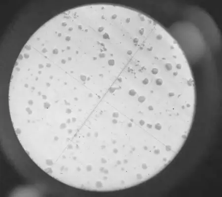
Performance tests were conducted on the test bars. The metallographic results of the casting body are shown in Figure 3.

Figure 3 Microstructure
7 Conclusion
Through the production of the first piece of the heavy ductile iron casting, the effectiveness and rationality of the gating and riser system were verified during the production process. The design of the gating system, which integrates filling, exhaust, slag removal and feeding, was further improved. The problems of surface slag inclusion, wrinkling and shrinkage porosity that are prone to occur in the shell molding process were solved. Due to the thick wall of the casting, the long solidification time and the high performance requirements, there are great difficulties in the production process. Through strict process control, selection of suitable raw materials, appropriate spheroidizing and inoculation treatment processes, and special pretreatment techniques, it is completely possible to produce high-quality large ductile iron castings.
Vigor has more than 20 years experience and the professional team in casting and forging processes. If any thing we can help or you have products need to be developed, please feel free to contact us at info@castings-forging.com


