
Knowledge
Development of Die-casting Process for the Rear End Cover of Motor Housing
The die-casting process of the rear end cover of the aluminum alloy motor housing was developed. In the early stage, the runner was reasonably arranged according to the product structure, and the filling and solidification analysis of the gating system was carried out by using numerical simulation software. During the actual production process, it was found that the gas holes in the castings were difficult to eliminate. According to the product structure, different solutions were adopted for different areas. For the gas holes in the thin-walled area at the end of the product where the slag pot could not be arranged, the exhaust insert and the increase of wall thickness were used to improve the fluidity of the aluminum liquid; for the dense gas holes in the thick-walled area at the end of the gating system, the cooling was strengthened to accelerate the local solidification and increase the thickness of the dense layer on the product surface; for the gas holes in the thick-walled area at the feeding port, the gating system was analyzed and the feeding was locally strengthened, etc. The trial production results show that the overall gas holes of the product were improved by using the optimized scheme, and the scrap rate was reduced. Keywords: Motor housing rear end cover; Die-casting process; Numerical simulation
The rear end cover of the motor housing is an important component in the power drive system of new energy vehicles [1-3]. Its main function is to support the motor rotor and fix the motor stator, and at the same time prevent external substances such as dust and water vapor from entering the motor. Therefore, there are certain requirements for the structural strength and air tightness of the product. At the same time, the bearing hole position of the product adopts local inserts after forming, and the mold needs to consider the positioning and pressing of the inserts, which increases the difficulty of mold making and production process debugging. Therefore, it is very important to ensure the stable production of the mold through the early design and later process improvement of the mold.
1. Casting structure and development requirements
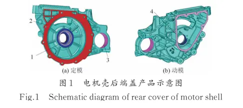
The motor housing end cover part of the new energy vehicle is shown in Figure 1. The part has a contour size of 397.98 mm × 91.48 mm × 286.46 mm, a die-casting weight of 5.71 kg, an average wall thickness of 8.06 mm, and a projected area of 74,759 mm². The casting material is ADC12 aluminum alloy. The overall wall thickness of the casting is relatively thick, with a maximum wall thickness of 33 mm and a minimum wall thickness of 4 mm, and the wall thickness is uneven. The bearing chamber position of the product adopts local inserts, and the insert material is 45# steel, which is quenched and tempered, with a hardness (HRC) of 24-30. All the external dimensions of the product must meet the assembly requirements of the drawing. The motor mating surface and the wiring box cover plate installation surface of the product have sealing requirements. The bearing hole and the half shaft hole install the motor rotor, and there are certain requirements for the exposed gas holes after processing. In addition, there should be no obvious burn marks or scratches at the corners, and the product should have no burrs or flash. The product requires air tightness testing, and the specific air tightness requirements are: the test pressure is 22 kPa, and the allowable leakage is <5 mL/min.
2. Mold development and design
2.1 Product parting line design
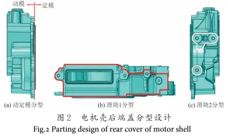
According to the product structure analysis, the appropriate parting line of the moving and fixed molds was selected. In addition, the product side is demolded in two directions, so the mold needs to be designed with two core-pulling sliders for parting. The parting line of the moving and fixed molds and the slider parting line of the product are shown in Figure 2.
2.2 Product wall thickness analysis
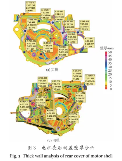
The wall thickness analysis of the motor housing rear end cover is shown in Figure 3. According to the product wall thickness, the analysis was carried out on the fixed mold side of the product. The left side has a small area with a relatively thick wall thickness, and the right half has a relatively thick overall wall thickness (see Figure 3a). Analyzed on the moving mold side of the product, the moving mold is a rib structure overall, and the thick-walled ribs are mainly on the left side (see Figure 3b). Therefore, the wall thickness of the product on both sides is extremely uneven. To ensure that there is sufficient aluminum material filling at the wall thickness position, the gate layout at the wall thickness position needs to be strengthened.
2.3 Gating system design
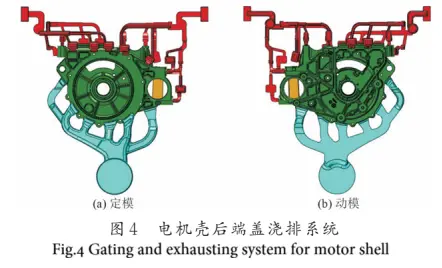
The design focus of the gating system is the selection of the gate. Generally, the position and form of the gate need to be determined according to the shape, structure, and precision requirements of the casting [4]. Based on the structural analysis of the product, the product can be fed on the side of the slider 1 and its opposite side. However, considering the critical positions of the product, except for the motor mating surface which is not affected by the entire product periphery, the bearing holes and half shaft holes are far from the side of slider 1, and the installation surface of the junction box cover plate is on the back of the slider on the moving mold side and is affected by the material blocking of slider 1. Therefore, the gate is arranged on the opposite side of slider 1 to ensure that the feeding position is close to the bearing holes and half shaft holes, and the installation surface of the junction box cover plate is not affected by the material blocking of slider 1. The inner gate layout is as follows: 4 inner gates are arranged on the machined end face on the opposite side of slider 1, and 1 inner gate is arranged on each of the non-machined positions on both sides to enhance the filling on both sides. At the same time, a bridge is set up in the middle of the outer circular hole of the product to pass the material. The final design of the gating system is shown in Figure 4.
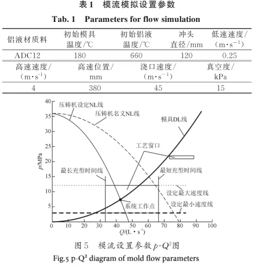
Magma simulation analysis was adopted, and the initial conditions for the mold flow analysis are shown in Table 1. The p-Q diagram was used to verify the rationality of the relevant processes, and the relevant process settings are reasonable as shown in Figure 5.
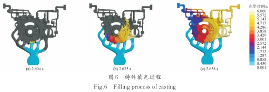
The filling process of the entire casting product was simulated and analyzed by Magma, as shown in Figure 6. It can be seen that when the aluminum liquid fills for 2.604 s, the metal liquid from the two inner gates near the main runner first fills the cavity (see Figure 6a); when it fills for 2.625 s, all inner gates start to fill the cavity (see Figure 6b); when it fills for 2.658 s, the entire casting is filled (see Figure 6c). During the entire filling process, the filling time of the metal liquid through the inner gates is 44 ms, and the metal liquid in the thick wall position of the product fills first, with no filling deficiency. The gating system meets the filling requirements of the product.
The overall gas pressure distribution of the casting is shown in Figure 7. The areas with higher gas pressure values are in the slag pot and overflow slot of the gating system and the thick-walled ribs of the product, indicating that there is a greater possibility of porosity in these positions. The solidification process of the product is shown in Figure 8. It can be seen that 3 s after the filling is completed, a few edges solidify (see Figure 8a); 12 s after the filling is completed, most of it has solidified (see Figure 8b); the slow solidification positions are the thick-walled areas of the product


According to the simulation results, it can be seen that this gating system can basically achieve the filling of the aluminum material in the cavity. At the same time, the gas pressure is mainly concentrated in the slag pot and some local non-machined ribs of the product. It is preliminarily determined to choose this gating and drainage scheme. In addition, due to the relatively thick overall wall thickness of the product and the uneven distribution of the wall thickness, local non-uniform cooling occurs, which can be used as a reference for designing the mold cooling system.
2.4 Mold Water Transport Design
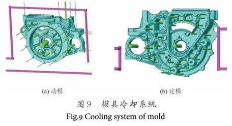
Cooling water is set in the thick-walled area of the casting to ensure the cooling effect of the thick-walled area and avoid the occurrence of shrinkage porosity and shrinkage cavities in this area. The periphery of the product adopts a straight cooling water transport, and point cooling is designed for other positions. At the same time, point cooling pins are used for core pins with a diameter of ϕ5 mm or more. The final cooling system is shown in Figure 9.
3 Die Casting Trial Production Process and Problems
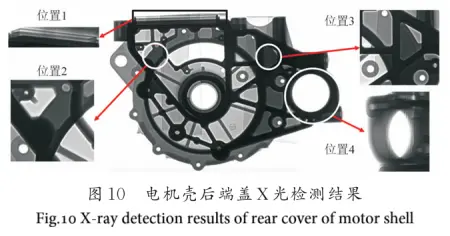
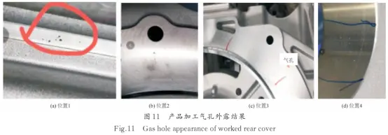
According to the design matching of the mold, a 16,000 kN Idra die casting machine was used for production. The punch diameter was selected as 120 mm, and the effective stroke of the injection was 620 mm. The mass of the aluminum liquid passing through the inner gate was 6.15 kg. The theoretical high-speed position was set at 380 mm, the height speed of the injection punch was 4 m/s, and the pressure-up position was set at 560 mm. These were used as the basic parameters for debugging and production. The surrounding equipment of the machine was fully automatic production equipment, which could effectively ensure the stability of the production process. During the actual production debugging, the high-speed position was appropriately adjusted to verify the product quality. Finally, when the high-speed position was 420 mm, the high-speed speed was 4.2 m/s, and the pressure-up position was 560 mm, the product quality was ideal. However, through X-ray flaw detection, it was found that there were still unstable porosity in some local areas. The porosity condition of the product is shown in Figure 10. The standard for internal gas shrinkage holes in the product: At position 1, the wall thickness at the end of the casting is less than 9.5 mm; at positions 2 to 4, the local wall thickness exceeds 9.5 mm, and the local standard is in accordance with the grade 2 standard for aluminum alloy wall thickness and gas holes. The post-processing appearance standard: At positions 1 and 4, there is no limit to the number of non-connected gas holes less than ϕ0.25 mm, and for non-connected holes less than ϕ2 mm×2 mm deep, there are no more than 2 per 100 mm length; at positions 2 and 3, there is no limit to the number of non-connected gas holes less than ϕ0.25 mm, and for non-connected holes less than ϕ1 mm×1 mm deep, there are no more than 2 per 100 mm length. It can be seen that the post-processing appearance standard is stricter than the internal standard. After production in this state and CNC processing inspection, it was found that the gas holes detected by X-ray were partially exposed after processing (see Figure 11), so further improvement is needed for the product gas holes.
4. Improvement of trial production issues
4.1 Improvement of gas holes on the side wall of the square hole
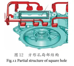
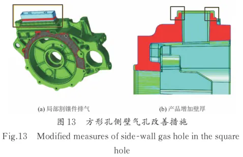
The local structure of the square hole is shown in Figure 12. The square hole is located at the water tail position of the casting and injection system, in the middle of the product. The local wall thickness of the square hole is 2.8 mm. Due to the inability to arrange slag packages around the square hole, the local gas is difficult to escape. At the same time, the wall thickness of the product is relatively thin compared to the overall product, so the local fluidity of the aluminum material is relatively poor, and cold material accumulation is likely to occur. To address the exhaust and reduce the accumulation of cold material, it is analyzed that using slag packages for exhaust and slag removal is the most effective method. Due to the product structure limitations, it is impossible to directly add slag packages, so a comprehensive solution is adopted. Figure 13 shows the improvement measures for gas holes on the side wall of the square hole. Measure 1 is to perform cut and insert treatment on the side wall where the gas holes are exposed after processing (see Figure 13a), using the mating parting surface of the mold insert to exhaust; Measure 2 is to thicken the local wall thickness to 3.8 mm (see Figure 13b), thereby improving the fluidity of the aluminum liquid filling and reducing the local accumulation of cold material. After the implementation of the comprehensive measures, it was found that the local gas holes were improved well and met the product quality requirements.
4.2 Improvement of gas holes on the motor mating surface
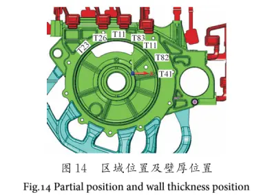
The gas holes at positions 2 and 3 are on the same surface of the product, as shown in Figure 14, and are located at the water tail side of the product's casting and injection system, which is also a relatively thick wall position. For thick wall positions of the product, the local solidification is generally slower. When the surrounding thin wall positions solidify, the local feeding channel is cut off, and internal shrinkage porosity is likely to occur. Additionally, according to production, the internal gas hole quality meets the standard requirements, but the exposure of gas holes due to processing does not meet the standard. Therefore, the improvement direction is mainly to avoid exposure. For the problem of exposed gas holes on the processing surface and at the water tail, the mesh pattern on the float surface can play a role in exhaust and cold material removal. Improvement method 1 is to add a mesh pattern on the local end face, but the improvement effect is not obvious. Therefore, for the shrinkage porosity in the thick wall position, it is necessary to locally increase extrusion. When the product is not completely solidified, extrusion pins are used for feeding. This method is theoretically feasible, but the dense gas holes in the product are relatively scattered, and a single extrusion pin cannot cover the entire area, while multiple extrusion pins are not practical. Therefore, this solution is not feasible. Considering the use of local mold temperature reduction, improvement method 2 is to add point cooling on the exposed end face to enhance local cooling and solidification, reduce local shrinkage porosity, and at the same time, lower the mold surface temperature to create a thicker dense layer on the product surface, thereby reducing the risk of exposure during processing. Figure 15 shows the improvement measures for gas holes on the motor mating surface. After adopting method 2, the internal quality of the product was improved, and the problem of exposed gas holes during processing was solved, meeting the processing quality requirements of the product.

4.3 Improvement of Gas Holes in the Half Shaft Hole
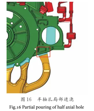
The gas holes at processing position 4 were inspected. The machining allowance of the product was found to be 0.6 to 0.8 mm, which is within the normal machining allowance range. The surrounding wall thickness was approximately 12 mm. The gas holes were located at the feed port of the gating system, and there was no issue of trapped cold material at the end. Additionally, water-cooling structures were arranged inside the hole to improve the cooling of the thick-walled area and prevent shrinkage porosity. Further analysis of the product's gating system revealed that although there was a runner at this position, it was directly opposite the product's draft allowance, as shown in Figure 16. This blocked the aluminum liquid from filling the local area, which might have caused the gas holes in that area due to insufficient filling.
To address the insufficient filling of the aluminum liquid and to reduce the moving mold and modify the gating system, the feeding at the half shaft hole position was strengthened. Method 1 involved widening the local runner gate to exceed the corresponding draft allowance. However, this resulted in the product directly hitting the fixed mold core pin, causing the core pin to be impacted and heated, leading to shrinkage cavities around it and frequent core pin breakage, increasing the mold failure rate. Method 2 involved bypassing the fixed mold core pin and the moving mold core pin by adding a runner between them and disconnecting the overflow to prevent the aluminum liquid from directly flowing along the overflow and causing backflow and entrapment. The improvement measures are shown in Figure 17.
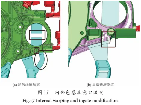
After improving the gate and the bridge according to Method 2, the gas holes in the half shaft hole were significantly improved.
5 Conclusion
Through the development of the die-casting process for the aluminum alloy motor housing rear end cover, a feasible feeding scheme was selected based on the product's parting structure and feeding principles. The rationality of the product's feeding scheme and gating system was analyzed using numerical simulation. Relevant measures were taken on the mold to shorten the project development cycle. By comparing the problems that occurred during actual production with the simulation results, the gating system of the product was further optimized, the forming process conditions were improved, and the quality of the castings was enhanced.


