Knowledge
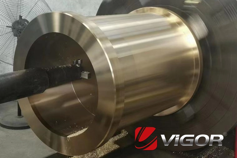
Copper Sleeves Fit Requirements (Copper Bushing)

1. Type of fit selection:
(1) Interference fit
Application scenarios: Heavy loads, impact loads, or high torque transmission requirements (e.g., gearbox bushings, fixed bearing housings).
Interference calculation: Usually 0.001 to 0.003 times the shaft diameter (e.g., for a Φ50mm shaft, the interference is approximately 0.05 to 0.15mm).
(2) Clearance fit
Application in sliding bearings: Rotating or reciprocating motion requiring lubrication (e.g., connecting rod bushings, hydraulic cylinder guide sleeves).
Recommended clearance: General conditions: 0.0005 to 0.001 times the shaft diameter (for a Φ50mm shaft, the clearance is 0.025 to 0.05mm).
High-speed/high-temperature conditions: Increase clearance to compensate for thermal expansion (e.g., clearance in the copper sleeve of an internal combustion engine connecting rod can reach 0.1mm).
Precise adjustment: Use H7/g6 (moderate clearance) or H8/f7 (larger clearance) fits.
(3) Transition fit
Light loads and high positioning accuracy requirements (e.g., instrument bushings), commonly use H7/k6 or H7/n6.
2. Key Design Parameters
(1) Surface Roughness
Shaft surface: Ra ≤ 0.8 μm (grinding process), inner hole of copper sleeve: Ra ≤ 1.6 μm (reaming/honing).
Reducing roughness can decrease wear, especially suitable for oil-free lubrication conditions.
(2) Thermal Expansion Compensation
The thermal expansion coefficient of the copper sleeve (≈ 18×10⁻⁶/℃) is usually higher than that of the steel shaft (≈ 11×10⁻⁶/℃).
For high-temperature conditions, additional clearance (Δd = original clearance + (α_copper - α_steel) × ΔT × shaft diameter) should be reserved.
(3) Wall Thickness Design
Minimum wall thickness ≥ 1/20 of the shaft diameter (e.g., for a Φ50mm shaft, wall thickness ≥ 2.5mm).
3. Lubrication and Wear Resistance Design
Lubrication channels: Open oil grooves (helical grooves, axial straight grooves) or oil holes to ensure that the lubricant covers the contact surface.
Self-lubricating copper sleeves: Copper sleeves embedded with graphite or PTFE (such as JDB bushings), allowing for a smaller fit clearance (H7/h6).
Surface treatment: Hard chrome plating on the shaft (thickness 0.02 to 0.05mm) or tin plating on the inner hole of the copper sleeve to reduce the coefficient of friction.
4. Key Points for Assembly and Maintenance
Control of Pressing Force: For interference fit, the formula for pressing force is: F = π × d × L × p × μ (d: bore diameter, L: fit length, p: contact pressure, μ: friction coefficient)
5. Typical Application Examples
|
Application Scenario |
Recommended Fit |
Interference |
Remarks |
|
Agricultural machinery connecting rod bushing |
H7/e8 |
0.05 - 0.10mm |
Regular grease lubrication |
|
Water pump bearing housing |
H7/s6 |
Interference 0.03 - 0.08mm |
Bore reaming after press-fitting to ensure concentricity |
|
Machine tool guide rail copper sleeve |
H7/g6 |
0.01 - 0.03mm |
Oil film lubrication, high precision requirement |
6. Failure Prevention
Overheating failure: Insufficient clearance leads to poor lubrication (copper sleeve surface ≤ 120℃).
Fatigue spalling: Excessive interference causes stress concentration. It is recommended to verify the contact stress through finite element analysis (FEA).
Corrosion wear: Select tin bronze (such as C94300) or nickel-plated surface in humid environments.
By reasonably choosing fit tolerances, lubrication schemes and materials, the service life of the copper sleeve can be significantly improved. For critical operating conditions, it is recommended to verify the fit parameters through tests.
Vigor has more than 15 years experience on production and supply of copper bushing, copper jacket and plate sheets. If you have any question, demand, related parts development or improve your supply chain, please feel free to contact us at info@castings-forging.com


