
Knowledge
Casting Process Design and Production Practice of the Valve Shell for the Main Steam Valve Regulating Valve (Part 1)
After analyzing the part structure, material properties, technical requirements and casting process difficulties of the CB2 main steam valve regulating valve shell casting, as well as considering potential casting quality issues, through the research on the cause of valve shell cracks, solidification zone feeding and the setting of cold iron in the solidification end zone, the common defects such as porosity and cracks in the casting process were effectively solved. A reasonable and practical casting process plan was developed, and the control of the manufacturing process was strengthened, improving the stability of the process and operation. After production verification, the overall quality of the valve shell was good, meeting the standard requirements, and the batch manufacturing of the CB2 main steam valve regulating valve shell was successfully achieved.
The main steam valve regulating valve shell, as one of the core components of the 620℃ ultra-supercritical thermal power turbine unit, not only has a large contour size and complex structure, but also has extremely high requirements for comprehensive performance. This valve shell is made of heat-resistant steel ZG13Cr9Mo2Co1VNbNB material (referred to as CB2). Due to the valve shell working in a high-temperature and high-pressure environment, the internal quality and dimensional accuracy requirements are extremely strict [1-3]. However, due to its complex structure and large wall thickness difference, the feeding difficulty during the casting process is extremely high. In addition, the CB2 material has a large tendency to crack, resulting in significant quality fluctuations of this valve shell. This paper deeply studies the casting process optimization scheme, ensuring the process quality and operational convenience, thereby achieving stable quality and batch production of the CB2 main steam valve regulating valve shell.
1 Technical Requirements for the Main Steam Valve Regulating Valve Shell
1.1 Casting Structure
The main steam valve regulating valve shell is a key component in 1000 MW secondary reheat units, operating under high temperature and pressure conditions. To ensure its stable and reliable operation in such harsh environments, extremely high standards are set for both its internal quality and external dimensions. The casting contour dimensions of the main steam valve regulating valve shell are 2545 mm x 2512 mm x 2511 mm, with a part weight of 22.5 t. It is a complex, irregular structure formed by the intersection of an irregular rotary body and two horizontal tubes distributed at 90°, with a main wall thickness of only 110 mm. Its structure is shown in Figure 1.
1.2 Casting Technical Requirements
The main steam valve regulating valve shell casting is made of CB2 material. The chemical composition and mechanical properties of the material are shown in Tables 1 and 2.


The valve shell must undergo 100% magnetic particle inspection and ultrasonic testing. When performing ultrasonic testing on the flange and sealing surface, a φ4 mm equivalent scan should be used, and no single or area defects are allowed. For the rest of the processed surfaces of the valve shell, all pipe openings, and lifting lugs, the single and area defects should not exceed 1300 mm²; for the rest of the non-processed surfaces, the single defect should not exceed 1300 mm², and the area defect should not exceed 3900 mm².
2. Technical Challenges and Solutions
Due to the large size and weight, complex structure, and extremely high quality requirements of the main steam valve regulating valve shell, the difficulty of batch production and manufacturing has been further increased. When designing the casting scheme, stable and easily achievable process measures must be adopted to ensure the quality of each product in batch production.
2.1 Difficulty in Feeding and Solutions
(1) Difficulty in Feeding the Valve Shell
The valve shell is large in size and complex in shape and structure. From the analysis of the part structure, the hot spots are scattered, and the thickness varies greatly. The conditions for sequential solidification feeding are poor. Moreover, the CB2 material, due to its high alloy content and wide crystallization range, has viscous molten steel, and it is prone to shrinkage porosity defects in the transition area during solidification and feeding. This valve shell has two thick and large areas that are difficult to feed: 1) The thick and large area at the bottom end of the pipe opening and the large hot spot at the middle flange part are prone to shrinkage porosity defects during solidification and feeding; 2) The middle part has a complex structure, and the hot spots are scattered at the intersection of the ribs and the transverse pipes, which is not conducive to sequential solidification feeding and the placement of risers.
(2) Solutions to Feeding Problems
Based on the structure of the valve shell casting, the risers are designed in layers as a whole; the riser positions are set at the thick and large hot spots of the casting. MAGMA simulation software is used to analyze the temperature field distribution of the valve shell, optimize the size and position of the risers and the added metal; in the areas prone to shrinkage porosity and shrinkage cavity defects, auxiliary risers or chills are set to enhance the feeding effect.
2.2 Risk of Cracking and Solutions
(1) High Tendency to Crack
This valve shell is made of CB2 material, which has many alloy elements and a large liquid contraction. The volume contraction is about 20% larger than that of general chromium-molybdenum castings. It is a high-chromium martensitic heat-resistant steel, and the casting stress and phase transformation stress are large, so the material has a high tendency to crack. Moreover, the wall thickness difference of the valve shell is large, with the largest hot spot in the middle area having a diameter of 360 mm and the smallest hot spot also in the middle area having a diameter of 110 mm. There are stress concentration problems at the locations with large wall thickness differences in the middle area and at the rounded corners where the pipes meet, and cracks may occur during solidification due to stress differences.
(2) Solutions to Cracking Problems
To further improve the material's crack resistance, a special heat treatment process for this valve shell is developed. During the manufacturing process, the temperature and time parameters during heat treatment are strictly controlled to eliminate casting stress and improve the material's microstructure, significantly enhancing the overall performance of the material.
At the junctions of the pipes and the areas with large wall thickness differences of the valve shell, additional metal is added and the rounded corners are enlarged to make the wall thickness cross-section smoothly transition and prevent stress concentration-induced cracks.
The valve shell is divided into sections to set up additional metal and risers to ensure the directional sequential solidification of the valve shell and prevent the formation of hot cracks. Since hot cracks are formed by the rupture of the liquid film during the solidification of the molten steel, setting up additional metal and risers allows the molten steel to be smoothly replenished during the cold shrinkage of the casting, preventing the liquid film from being torn and causing hot cracks.
2.3 Dimensional Accuracy Control
(1) Difficulty in Dimensional Control
The valve shell is large in size and complex in structure, with inconsistent shrinkage in the upper and lower parts and high dimensional accuracy requirements. The main core in the middle of the valve shell is very high, and the different strengths of the sand cores have an impact on the shrinkage, making it easy to have deviations in the wall thickness dimensions. There are two large ribs in the middle, which are not conducive to the parting and mold removal of the valve shell. The use of core assembly forming methods increases the difficulty of dimensional control.
(2) Solutions
(No specific solutions are provided in the original text for this section.) Through DOE simulation with different boundary conditions, the linear shrinkage value that best matches the enterprise is selected. A numerical control model is adopted to improve the dimensional accuracy of the model. To address the issue of the main core height in the middle, a segmented core structure is designed and a core assembly forming method is adopted to adapt to the complex structural characteristics of the valve housing. Three-dimensional data detection is conducted on the model and cavity to ensure the dimensional accuracy and operational stability during the molding process.
3. Valve Housing Casting Process Design
Batch production manufacturing places higher demands on the design of casting processes, which requires multiple trials to verify the stability and repeatability of the process, thereby ensuring stable and high-quality production of the product.
3.1 Design of Casting Feeding Scheme
Based on the temperature field distribution of the valve housing part simulated by MAGMA software as shown in Figure 2, the risers, gates and chill irons are reasonably designed according to the part structure, module size and casting process design principles [8].
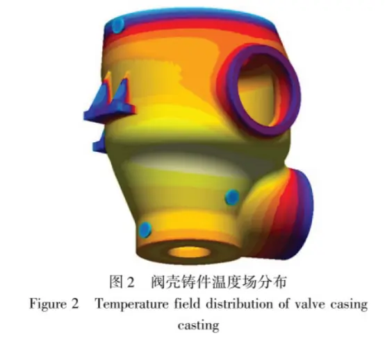
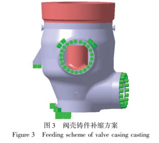
The casting process design for this valve housing: According to the complexity of the valve housing structure and the material properties, the feeding is carried out in sections and zones, dividing it into three layers. The bottom horizontal pipe area is the first layer, the area around the middle horizontal pipe is the second layer, and the upper large flange is the third layer. The size, shape, and position of the risers are designed respectively based on the hot spots and feeding requirements of these three layers.
The ratio of the riser volume to the casting volume, M riser / M casting, is approximately 1 to 1.2 [9].
A reasonable riser design ensures that all parts of the casting receive adequate feeding during solidification. Cold iron is used to create artificial end zones by sectionally isolating different areas, controlling the cooling rate of different parts of the valve housing and promoting sequential solidification, resulting in a denser structure. With the MAGMA solidification simulation software, the design of the feeding and risers was repeatedly optimized. The final overall feeding and riser design for the valve housing is shown in Figure 3.
3.2 Design of the Pouring System
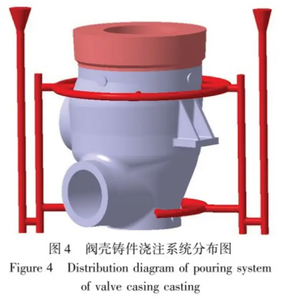
The material of the main steam valve regulating valve shell casting has poor fluidity and is prone to oxidation inclusions. Designing a reasonable pouring system and controlling the pouring quality are the keys to ensuring the quality of the valve shell. This valve shell adopts a double-layer nozzle design, which can effectively avoid the risk of pouring fractures. On the basis of the double-layer nozzle, the opening degree is increased. This valve shell uses two φ120mm straight nozzles and eight φ100mm inner nozzles. Combined with the actual production situation, single-bag φ80mm double-bag eye pouring is adopted, making ΣS bag eye: ΣS horizontal: ΣS inner ≈ 1:2:3, and the steel liquid rising speed is 16mm/s. This pouring scheme can ensure that the steel liquid enters the cavity smoothly and quickly, reducing the problems of entrained gas and inclusions caused by unstable filling. Argon gas protection pouring is also adopted to effectively reduce the oxidation degree of the steel liquid [10]. According to the batch production practice verification, this pouring system can make the steel liquid rise quickly and smoothly, which not only improves the pouring efficiency but also further ensures the pouring quality of the valve shell. The design of the pouring system is shown in Figure 4.
3.3 Analysis of Solidification Simulation Results
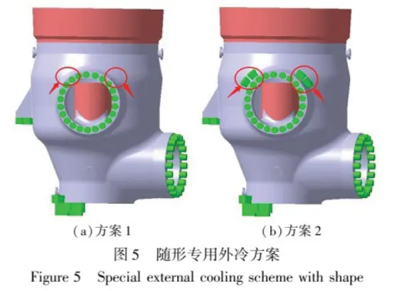
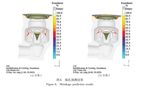
Based on the solidification simulation software for casting processes, the casting process was optimized for the valve shell prone to UT defects. Two comparison schemes were designed as shown in Figure 5. Firstly, the shrinkage cavity Soundness criterion was used for analysis. Scheme 1 showed obvious shrinkage cavity indications at the positions marked by circles in Figure 6(a). After optimization, in Scheme 2, a conformal dedicated external cooling was set at this position, and the simulation showed no indication at this location as circled in Figure 6(b), thus resolving this shrinkage cavity defect.
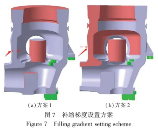
The Niyama criterion was used to analyze Scheme 1 and Scheme 2. In Scheme 1, a 1:20 feeding gradient was set at the arrow position in Figure 7(a), while in Scheme 2, a 1:10 feeding gradient was set at the same position, as shown in Figure 7(b). Additionally, external cooling was applied to make the microstructure more compact. The Niyama results indicated that when the Niyama parameter was set at 0.3, obvious porosity defects were displayed at the circled position in Scheme 1, as shown in Figure 8(a); in Scheme 2, only a few point-like displays were observed at the circled position, as shown in Figure 8(b).
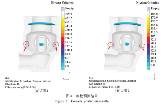
Based on the comparative analysis of the above simulation results, Scheme 2 was ultimately selected. This scheme only showed point-like defect displays at local positions except for the riser location, and there were no obvious shrinkage cavity or porosity defect displays on the valve shell as a whole.
Vigor has more than 20 years of experience and a professional team in casting and forging processes. If anything we can help or you have products need to be developed, please feel free to contact us at info@castings-forging.com


