
Knowledge
Analysis and Optimization of the Casting Process Design for the Medium Pressure Inner Cylinder in CB2
The inner cylinder casting of the steam turbine has a large wall thickness and narrow steam passage in the inner cavity, which is prone to sand sticking. The reasons for the shrinkage porosity defects in the initial casting process were analyzed, and the solidification process was simulated using MAGMA software. The casting process plan was optimized in a targeted manner. After the production verification of the optimized casting process, the casting quality was good and met the technical requirements. Compared with the initial plan, the casting process yield increased by nearly 20%.
As one of the core equipment in thermal power plants, the development focus of the steam turbine industry lies in how to improve the thermal efficiency of steam turbine units. The improvement of thermal efficiency is closely related to the temperature of main steam and reheat steam. When the temperature of main steam and reheat steam increases from 580 ℃ to 620 ℃, the thermal efficiency can be increased by about 4% to 6%. During the five years from 2013 to 2018, 620 ℃ ultra-supercritical units developed rapidly. However, with the continuous improvement of environmental protection and energy conservation requirements, thermal power units around the world began to pursue efficient, clean and low-emission power generation technologies. CB2 material, which has excellent thermal conductivity, low thermal expansion coefficient, good resistance to intergranular corrosion and stress corrosion, gradually replaced the traditional 12%Cr martensitic heat-resistant steel and became the material of choice for large key cast steel parts of the second-generation ultra-supercritical steam turbines [1-2].
However, at present, large cast steel parts made of CB2 material, such as high-pressure intake cylinders, medium-pressure inner cylinders and main steam regulating valve shells, still have problems such as unstable quality control of castings. This paper analyzes the causes of shrinkage porosity defects in the original casting process of the medium-pressure inner cylinder of CB2, adopts the casting process method of wall subsidies and wall risers to solve the shrinkage porosity problems at the T-shaped platform and pipe openings, predicts its quality by numerical simulation technology, and verifies it through actual production. Finally, qualified products are obtained, achieving the goal of improving quality and reducing costs [3-4].
1 Structural Characteristics and Technical Requirements of the Intermediate Pressure Inner Cylinder
1.1 Structural Analysis
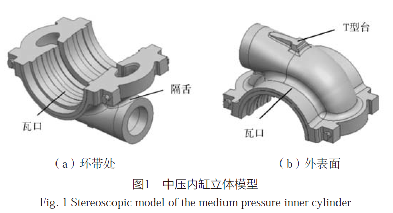
The specific structure of the intermediate pressure inner cylinder is shown in Figure 1. Its outline dimensions are 2,420 mm × 1,674 mm × 1,268 mm. The net weight of the upper half is 8,430 kg, and that of the lower half is 8,570 kg. The maximum wall thickness is 300 mm, and the minimum wall thickness is 85 mm. There are many internal annular bands with different radii, making control difficult. The overall quality requirements are strict.
1.2 Material Analysis
The material of the medium-pressure inner cylinder is ZG13Cr9Mo2Co1VNbNB-Ⅱ, abbreviated as CB2. The chemical composition requirements are shown in Table 1. During the finished product analysis, impurity and gas content analysis are required, among which Cu ≤ 0.10%, As ≤ 0.025%, Sb ≤ 0.001%, H ≤ 7×10⁻⁶, O ≤ 9×10⁻⁵, with strict requirements.

Mechanical property test blocks are required to be cast integrally with the main body and must not be disconnected from the main body during the heat treatment process. After heat treatment, the test blocks are cut off and processed into samples for mechanical property testing. The requirements for the indicators are shown in Table 2. Additionally, the high-temperature creep strength at 650 ℃ and 125 N/mm² is required to be greater than 100 hours.

1.3 Non-destructive Testing
100% UT for the medium-pressure inner cylinder, with the flange and steam passage areas accepted at level 1. Testing sensitivity: Φ2.4 mm for machined surfaces and Φ4 mm for rough surfaces; MT for all surfaces of the medium-pressure inner cylinder.
2. Analysis of Technical Challenges in Medium-Pressure Inner Cylinder
2.1 Material Analysis
The density of CB2 material is 7.8 g/cm³, with a solidus temperature of 1,482 ℃ and a liquidus temperature of 1,510 ℃. It has a complex chemical composition with many alloying elements, including contaminating elements such as Co, easily oxidized elements like B and N, and a narrow range of required composition. Despite its high creep strength and thermal resistance, the molten steel has poor fluidity and strong high-temperature oxidation, making it prone to slag inclusion defects. Moreover, the hot spots at the bottom T-shaped platform, tongue position, flange of the midsection, and the intersection of steam channels are scattered and isolated, making it difficult to achieve self-feeding. The material contains a relatively high amount of V, which increases the tendency for cracking. The main type of crack is cold cracking, so preheating is necessary for gas cutting, carbon arc cutting, and welding, with a preheating temperature of ≥ 300 ℃.
Heat treatment requirements for the casting: normalizing temperature ≥ 1,040 ℃, and final stress relief or final tempering temperature ≥ 730 ℃. The room temperature microstructure after heat treatment is lath martensite. Some data suggest that if there are many casting defects, the multiple tempering processes caused by subsequent repair welding will lead to a significant decrease in hardness and make it difficult to meet the technical requirements for strength [5]. Therefore, a reasonable casting process design not only avoids the need for defect repair welding but also ensures an adequate margin of strength.
2.2 Structural Analysis
(1) The medium-pressure inner cylinder as a whole is approximately in the shape of a "C", with thick flange walls and small variations in wall thickness at the steam channel positions, mostly uniform at 85 mm, as shown in Figure 2. This structure is nearly of the same geometric modulus, with a large difference in feeding gradients. During solidification, it is difficult to achieve self-feeding and sequential solidification, making it prone to axial shrinkage porosity.
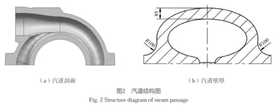
(2) The opening part of the steam passage (including the machining allowance) is only about 104 mm. After the casting is poured, the sand core of the steam passage is completely surrounded by molten steel, with poor exhaust performance and difficult cooling, which is very likely to cause sand sticking or even sintering, making it impossible to remove the sand. At the same time, the cross-sectional profile of the inner cavity of the steam passage varies with the angle of the cross-section, and the steam passage structure is relatively complex and closed. The core insertion and core lowering operations are rather complicated, and the sand core is not easy to be fixed during the core lowering process, which is very likely to cause core deviation. It is also very difficult to inspect the size of the cavity.
3. Design of Casting Process and Numerical Simulation for Medium Pressure Inner Cylinder
CB2 material is special with high crack sensitivity. To avoid large-scale welding repair and prevent crack formation and propagation, and considering the strict requirements for surface and internal quality, the gating system should be placed on the machining surface during the design of the casting process. Removing the riser root by machining is beneficial to prevent crack formation. Additionally, numerical simulation methods should be used to verify the rationality of the casting process and reduce defects, thereby avoiding crack problems caused by defect removal and welding repair.
3.1 Design of Casting Process Scheme
The position of the parting surface in the casting process design determines the dimensional accuracy and molding efficiency of the casting [6-7]. The flange surface of the medium pressure inner cylinder is the position with the maximum wall thickness and also the machining surface. Using it as the parting surface, the casting process scheme is designed with the casting part facing down. This not only facilitates the feeding of thick and large hot spots but also makes it easier to cut off the risers. At the same time, the entire casting is located in the lower box, which is convenient for molding and box closing.
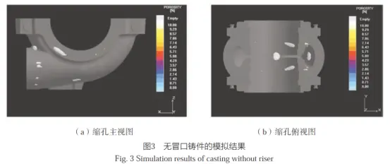
The model was built using UG software and imported into MAGMA simulation software. The number of mesh divisions was 20 million. The solidification simulation was directly conducted on the casting without risers, and the simulation results of shrinkage cavities are shown in Figure 3. The shrinkage cavity positions are mainly concentrated at the valve seat, tongue, and T-shaped platform, etc.
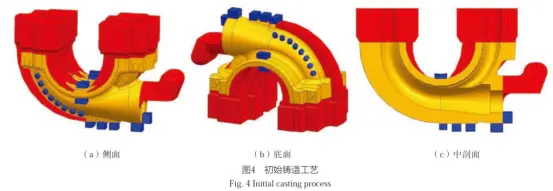
Based on the location of shrinkage cavities, the casting process plan is designed as follows: (1) The round-up method is adopted, and a riser following the shape is designed on the upper part of the flange. The dual effects of atmospheric pressure and the self-weight of the riser are utilized to enhance the steel liquid feeding capacity of the casting. Additionally, a human-made feed is added below the riser to feed the flange and the main body of the casting. (2) Long strip feeds are added to the outer surface of the steam passage to feed the lower part of the steam passage. (3) A blind riser is used above the steam passage opening to feed the tongue part. (4) A blind riser is used inside the steam passage to feed the T-shaped platform position, and an external cold iron of reasonable thickness is set on the outside. (5) Different specifications of external cold irons are used for zoning, and combined with the blind and open risers for feeding.
In terms of molding methods, the "main mold + core hanging" molding method is adopted. The main mold cavity does not need to make other core boxes, and no draft angle needs to be set. For individual structures that affect the mold lifting, a combination of foam and live material is used to achieve the integrated casting of the inner cavity sand core and improve the dimensional accuracy of the sand mold. The final casting process plan is shown in Figure 4.
3.2 Numerical Simulation of Casting Process
The structure of this casting is complex. MAGMA software was used to simulate the temperature field and shrinkage cavities during the solidification process of the casting to verify the feasibility of the casting process design, reduce the risk of defects in the actual production process, and provide effective data support for process optimization. The components in the casting process model were converted into STL files and imported into MAGMA software in sequence for meshing, with a mesh quantity of 20 million. The simulation results are shown in Figure 5. It can be seen that there are no shrinkage cavity defects in the casting body, and the safe height of the riser was measured to be 80 mm.
The simulation results of shrinkage porosity show that there is a large area of blocky shrinkage porosity concentration above the pipe opening and at the T-shaped platform position. According to the non-destructive testing requirements, the quality requirements for the flange and steam passage area are strict, and they are accepted at level 1. Such shrinkage porosity simulation results will definitely affect the product quality. Analyzing the reasons, although a human-made subsidy was added at the bottom of the cylinder, due to the thick T-shaped platform, the wall thickness change is large, and the isolated hot spot here has not been completely eliminated. On the other hand, due to the structure of the cylinder itself, the blind riser cannot be set directly above the pipe opening, and in order to avoid the thermal influence of the blind riser on the flange area, the blind riser has to be shifted away from the cylinder pipe opening, which increases the distance for feeding and greatly reduces the feeding effect of the blind riser.
3.3 Optimization of Casting Process Scheme
The optimized scheme adopts the wall subsidy and wall riser scheme. As shown in Figure 6, a "wall subsidy" close to the inner cavity wall is set at the cylinder ring band, with a riser set above it to concentrate the hot spot. The open riser feeds the entire part through the wall subsidy, and this "D-shaped" subsidy acts as an inner cavity rib, preventing deformation. Human-made subsidies are added on both sides of the outer wall of the inner cylinder to form a feeding channel for the T-shaped platform. Compared with the initial scheme, the feeding channel distance is shorter and the effect is more obvious. A subsidy is added between the flange and the pipe opening to form a feeding channel. For the uniform wall thickness area of the inner cylinder steam passage where the feeding gradient difference exists, a human-made conformal subsidy is designed using the rolling circle method. Cold iron is set on the outside of the steam passage. The combined use of subsidies, risers, and cold iron forms distinct feeding channels to feed the scattered and independent hot spots of the cylinder, effectively avoiding the defects of the T-shaped platform and pipe opening in the initial scheme. Additionally, a rib is set at the fillet transition area between the outside of the steam passage and the main body of the casting to control crack formation.
--------------------------------------
The simulation results of the optimized process plan are shown in Figure 7. All shrinkage cavities exist in the wall-type chills and risers, and are far from the ring band position. There are no shrinkage cavity defects in the casting body. The temperature field results indicate that the overall solidification trend is sequential, and the use of external chill has taken effect. From the simulation results of shrinkage porosity, there are no large blocky shrinkage porosities as in the initial casting process plan. Most of them are non-dense point-like shrinkage porosities, which can be ignored in actual production.

4 Key Control Points in the Manufacturing Process of the Medium Pressure Inner Cylinder
4.1 Metallurgical Aspects
The metallurgical process is "electric furnace rough refining + LF refining + VD vacuum refining". The chemical composition is controlled as per Table 1. Elements such as V, Nb, and Cr in the molten steel can form stable nitrides with N. However, their affinity for oxygen is greater than that for N. Additionally, B has a strong affinity for O. Therefore, to increase the solubility of N in the molten steel and control the content of B, strict deoxidation is necessary. Due to the strict control of Al content, Al is used as the final deoxidizer in appropriate amounts, which can control O while improving the alloy yield. The molten steel weighs 23,500 kg, and the tapping temperature is 1,580 to 1,590 ℃.
4.2 Molding Aspects
All surfaces of the medium pressure inner cylinder need to undergo UT and MT inspections, especially the non-destructive testing quality requirements for the steam passage area are strict. Once the steam passage is severely adhered with sand, it will have a significant impact on the quality during the sand removal process. To avoid the problem of sand adhesion in the steam passage, the inner cavity core is rammed using the method of CO2 hardening combined with Verkote new chromite sand. The core bone inside the steam passage core is made by welding hollow steel pipes together, with holes drilled around the steel pipes and hollow nylon ropes wound around the outside, which is conducive to gas exhaust. The hardening time of the sand core is controlled by the timing of CO2 gas injection. The overall core bone helps to fix the sand core and prevent it from floating. The accuracy of core insertion is ensured by combining the positioning core head with the cavity inspection template.
Since the coating used in this factory is alcohol-based zirconium silicate powder coating, to avoid the formation of surface pores, the cavity and the core lifting coating are applied at least four times. After each application, it needs to be ignited and dried thoroughly before being ground smooth for the next layer.
4.3 Pouring Process and Cleaning
Single-bag pouring is adopted, and a three-layer pouring system is designed, with two inner gates in each layer. The bottom layer is a bottom return type, while the other two layers are side entry types. The bottom return type pouring system facilitates the smooth and slow flow and rise of molten steel without causing strong impact. Due to the smaller wall thickness at the lower part of the mold, the liquid surface rises quickly to the height of the second layer side entry pouring system, which can reduce the occurrence of splashing and gas entrapment [8].
To prevent alloy oxidation during the pouring process, the mold cavity is filled with argon gas 30 minutes before pouring. The oxygen concentration in the mold cavity is measured with a portable oxygen detector to be below 5%, and argon gas protection is maintained throughout the pouring process using an argon gas protection ring and argon gas blowing pipes.
Based on the liquidus temperature of 1,510 ℃ for CB2 material and relevant production experience, the pouring temperature is set at 1,545 to 1,560 ℃. Due to the presence of V in the material, which is prone to cracking, the holding time must be strictly controlled to avoid cracking caused by premature box removal. After the pit is formed, the riser is preheated according to the dedicated riser cutting process, and then the riser and the sprue are hot-cut and the sprue is removed. During the entire cutting process, the temperature of the casting must not fall below 300 ℃.
5 Production Verification
After the heat preservation and boxing process, no adhered sand sintering was found in the steam passage cavity of the medium-pressure inner cylinder during the cleaning process. No shrinkage porosity, cracks or other casting defects were detected by UT testing after rough and finish machining. The dimensional inspection also met the drawing requirements. After heat treatment, the performance inspection was qualified, and the test results are shown in Table 3. This product meets the technical requirements, indicating that the optimized casting process, such as the design of the wall riser and the feeding allowance, the placement of the cold iron, and the anti-adhered sand and exhaust measures, are all effective. The manufactured casting is shown in Figure 8.

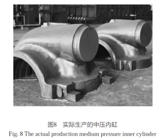
Table 4 shows the comparison between the optimized and initial schemes. The application of wall subsidies and wall risers not only avoids the occurrence of casting defects but also reduces the pouring weight by 5,000 kg. The process yield of the casting is increased by nearly 20%, and the ratio of net weight to pouring weight is improved by nearly 10%, thus reducing production costs.

6 Conclusion
(1) The simulation results of the two processes, namely the conformal riser and the wall riser, indicate that the use of wall subsidies and wall risers can more effectively address the casting process issues of the medium-pressure inner cylinder, such as the dispersion of hot spots and the low efficiency of blind riser feeding, significantly reducing the occurrence of shrinkage porosity and shrinkage cavities, and improving the product quality of the medium-pressure inner cylinder.
(2) The optimization and improvement of the casting process for the medium-pressure inner cylinder have increased the casting yield rate by nearly 20%, significantly reducing production costs.
Vigor has more than 20 years experience and the professional team in casting, die-forging and the post treatment processes. If you have any question or products need to do, please feel free to contact us at info@castings-forging.com


